Lessons in Minecraft's Redstone Logic. Lesson Two: Basic Logic Elements
\wipes dust off the tome** Have you missed classes at the School of Red Logic Minecraft? Missed? Great. Hungry for knowledge learners - what could be better?
Disclaimer. It is highly recommended to read the previous lessons before reviewing this one:
Lesson One: Repeater / Diode / Delay
[cut]
Instead of an Introduction
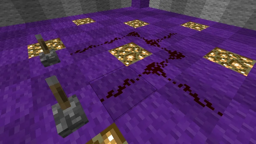
The first idea when I sat down to write this lesson was, "Hmm... What if, instead of that small and narrow room, we built something bigger and sturdier?" The first version looked like this:
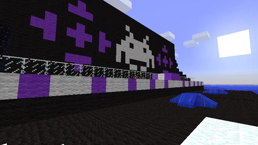
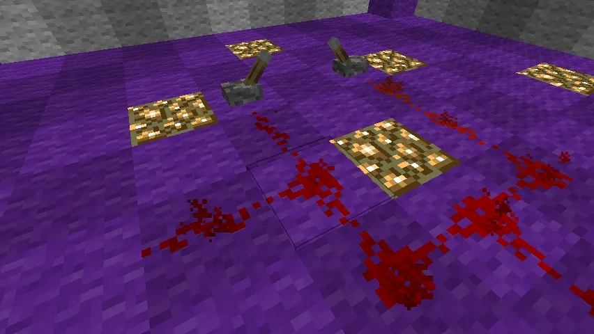
I looked at it, didn't like it, and decided to redesign. In the end, it turned into this cute research complex:
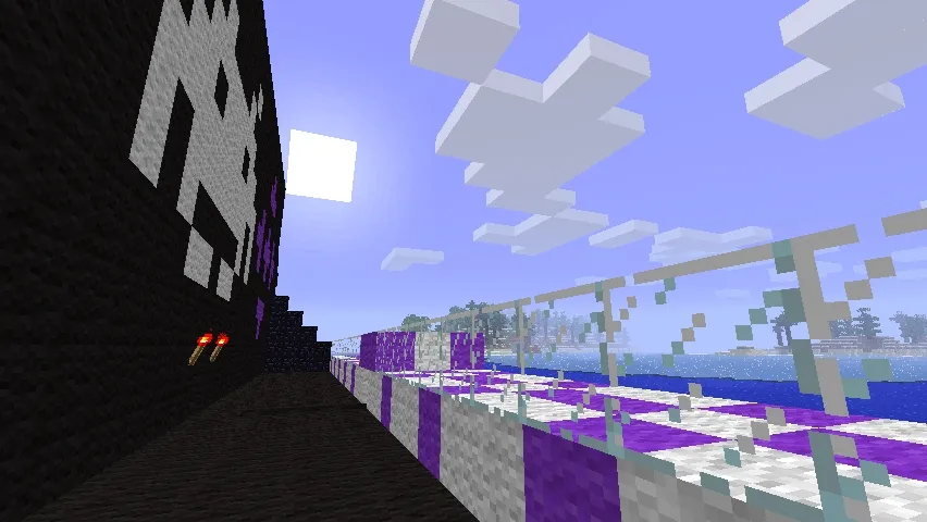
Even without pistons, it wasn't excluded:
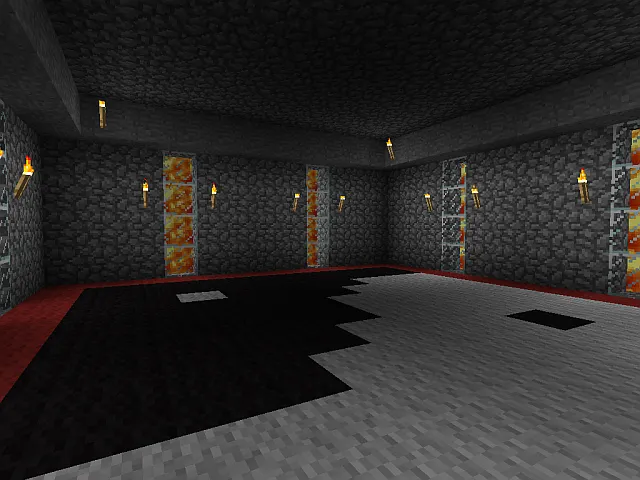
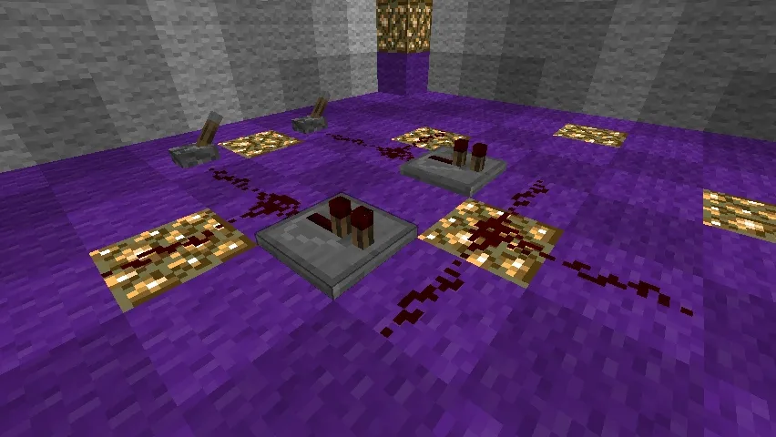
Inside, everything is quite modest:
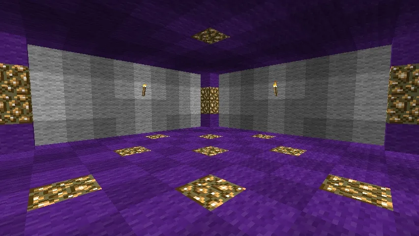
Even too modest. For a normal flight of fancy, this is lacking. But that's not the point; I will rebuild it by the next lesson. Let's get started.
Chapter 1. Transferring Signal Vertically
In the previous lessons, we only ran wires across flat surfaces or over small stepped obstacles. But what if we need to transfer a signal strictly down or strictly up?
Let's say, such a situation
As an option, we can build a spiral staircase from blocks:
Something like this
Rough. It's gone. Boring. Not our method. There is a more elegant option. It is smaller (2×1 vs. 2×2) and does not require adherence to the "Fifteen Rule" (the signal only spreads out fifteen blocks from the source; if you don't remember, refresh your memory with Lesson Zero).
It is worth mentioning right away that this option comes in two schemes:
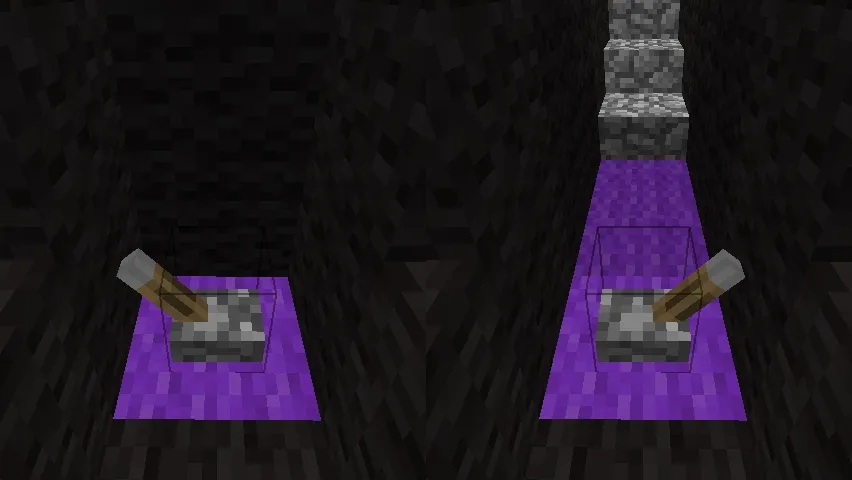
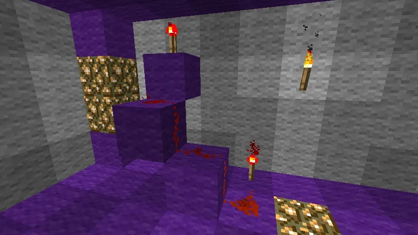
Scheme "Signal From Top to Bottom"
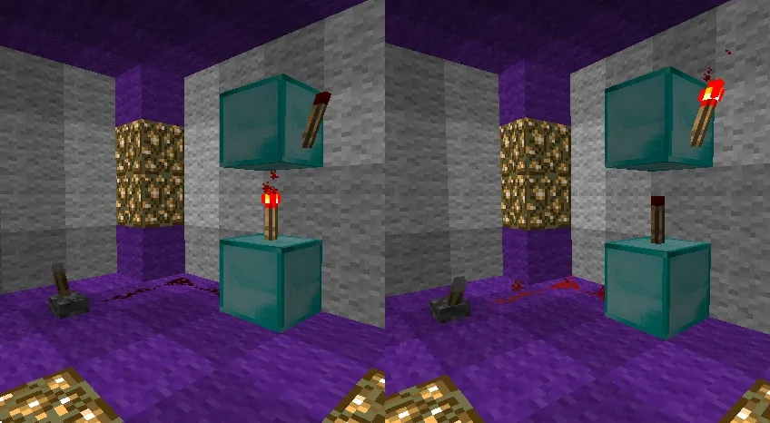
Scheme "Signal From Bottom to Top"
Note. No, this is not a three-dimensional picture that requires squinting to perceive. Get used to it; there are still tons of double, triple, and even quadruple pictures ahead. They differ in signals, so look for differences in wires, torches, and levers.
Chapter 2. Basic Logic Elements
Now let's move from general theory to the truest practice, focusing on the basic logic elements that can be used to construct almost any large logical operation.
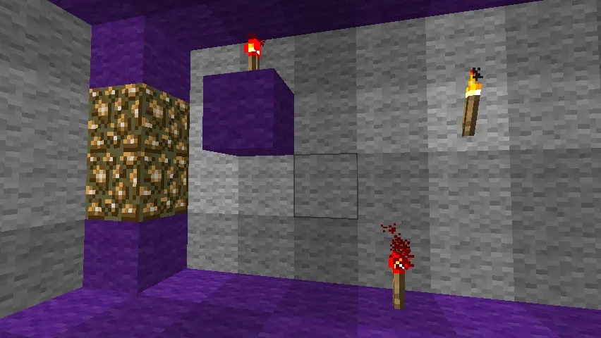
Connecting Block
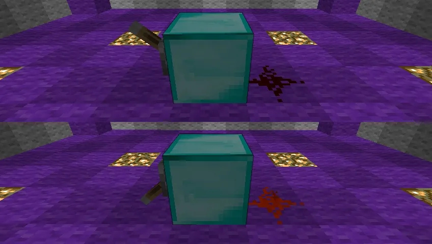
This block is very useful for hiding all the circuits behind walls. You hang a switch, attach a torch to it, and – voila! – you can transmit a signal through the wall where all the Red Magic will take place.
Inverter
An element already familiar to us from Lesson Zero. It can be used to invert the signal or as part of an amplifier to bypass the Fifteen Rule. The latter option faded into obscurity along with the introduction of the Diode in version 1.6.
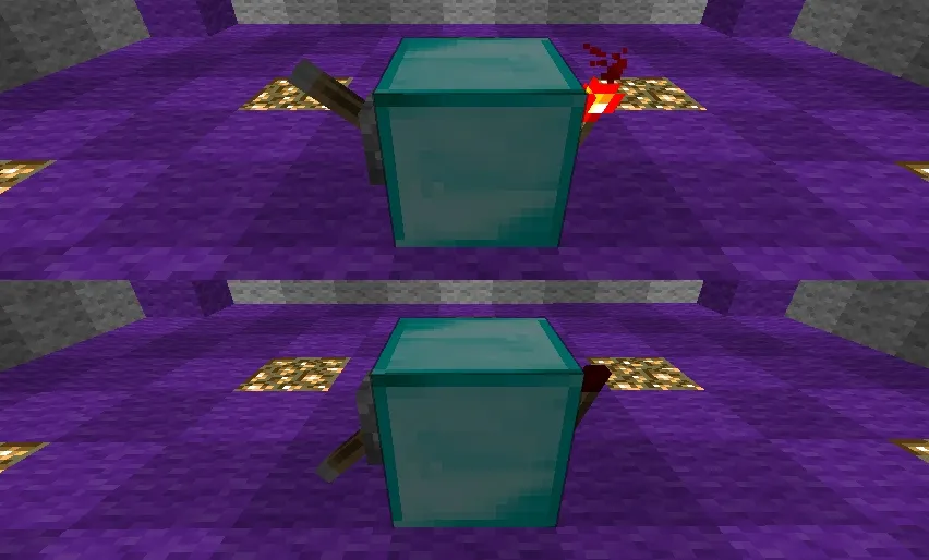
At first glance, this scheme is no different from the previous one, except that here a torch is used instead of sand. Actually, this difference encapsulates all the magic: in the first scheme, a signal simply comes from the block to the wire, while in the second, the torch receives it and changes it to the opposite.
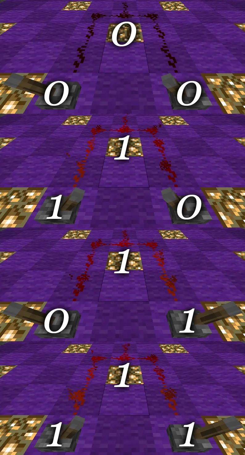
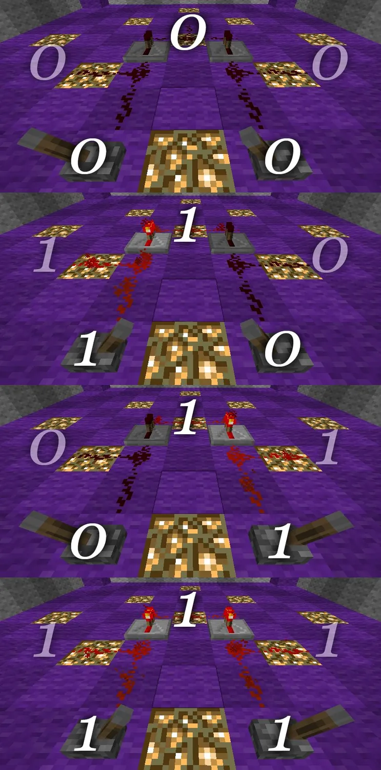
AND
Let's start with the AND element. You can learn more about the element itself in Discrete Mathematics and Mathematical Logic lessons. Or in some Scheme Engineering or Radio Engineering class. As a last resort – there's Wikipedia.
To put it briefly, the AND element outputs one if both signals entering it are equal to one.
The AND element schematic is quite simple:
To demonstrate the operation of the element, I'll run a wire from the output closer to the switches:
It works as expected:
It can be used, for example, so the door only opens when both switches are down.
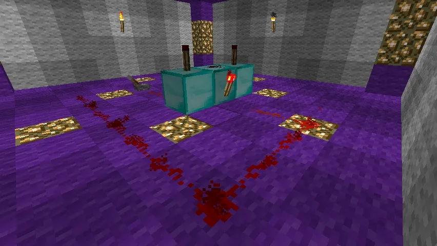
AND-NOT
AND-NOT elements simplify the life of circuit designers by not requiring additional equipment if they need an inverted signal from an AND element.
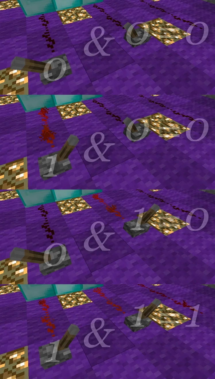
In the case of the AND-NOT element, this means that the wire will glow only if both switches are off.
Here, it’s already visible
But it’s worth demonstrating other variations as well:
Indeed, the output (left wire) lights up only when the switches are off.
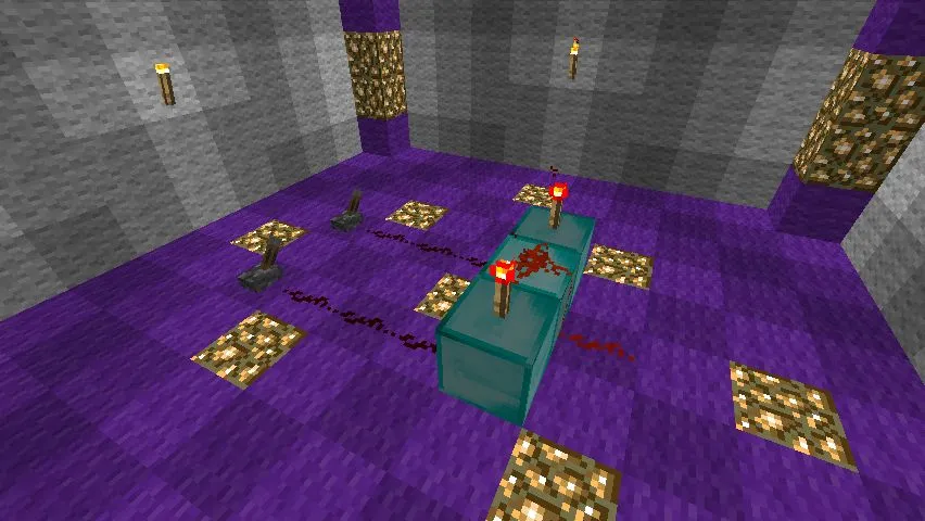
OR
The OR element. Works even simpler: it outputs one at the output if at least one input has a one. During the work on this subsection, it was found that it has quite diverse schematics. Depending on the player's wealth and the purposes for using the element, we can highlight three types of schematics. Let's start with the simplest.
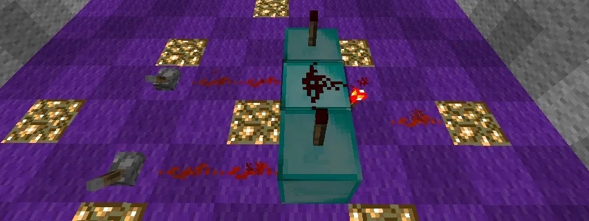
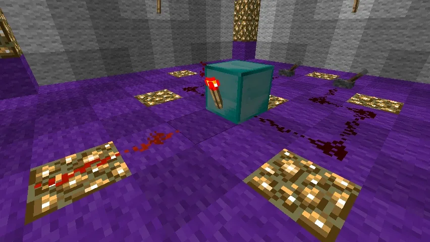
Lever Schematic
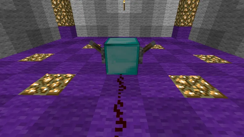
The diamond cube has hit the warpath. Missing a smoking cigar.
That’s exactly why it’s considered simple. The scope of application for this piece of art is still unclear to me, however, this schematic is listed in Minecraft Wiki, so I thought it was worth mentioning. Yes, I know what you're thinking: to stick wires in instead of switches.
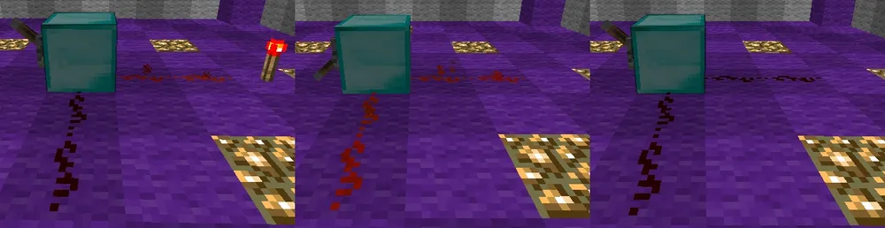
Poker Face performed by Red Sand
I tried. The result is the same.
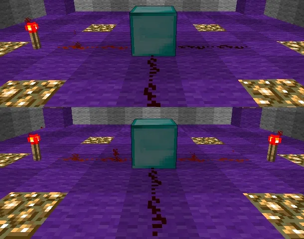
The mind also whispered that one could try replacing one of the wires with a switch...
And not a single hack was given that day
...but something didn't help. It only worked well on the combination 0˅0. That was irony, just so you know.
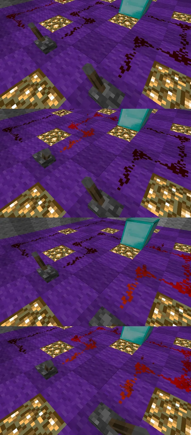
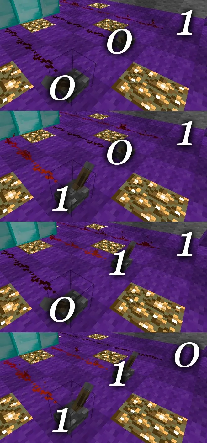
Wire Schematic
In place of the lever schematic comes a truly functional and actively used everywhere – wire schematic. It boasts simplicity and low equipment requirements (only Red Sand is needed).
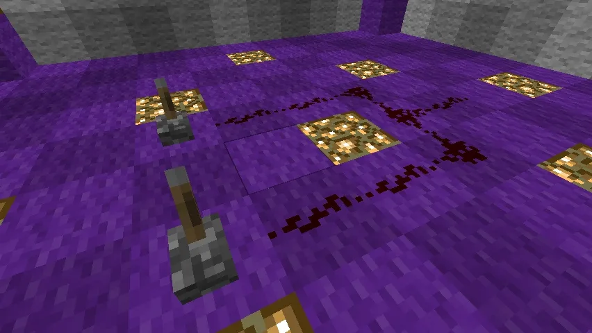
And here’s how it works:
An ideal schematic. Though there is...
The Problem of Getting an Actual Signal from the line
...which may arise in complex schematics. Suppose we fed two signals to our OR element, but we urgently needed the right one in another part of the schematic for some super important operations, and naively we did this:
However, when we pulled the left switch, a one appeared on our branch, which was supposed to indicate a zero:
:(
Sadness, trouble, sorrow.
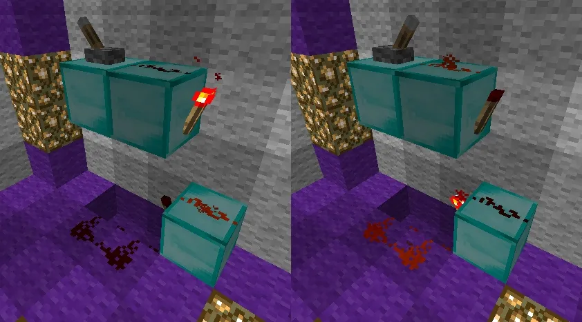
Diode Schematic
In pondering a solution to this problem, I spent a long twenty seconds. After that, I pulled two diodes out of my backpack and soldered them into the schematic:
In the first lesson, I already explained how diodes work. In this case, they work just as they should:
So here you have the first discovery of the Experimental Center at the Laboratory for Research of the Nature of Red Sand (who got the joke – raise your hand :3).
OR-NOT
The OR element also has its own ***-NOT variation. It's built ridiculously simply:
And it works the same way:
Instead of a Conclusion
That's it for today, folks. By now, you can already build a not too complex schematic that will do something very cool. For example, to open an iron door (which, by the way, cannot be opened any other way except with Red Sand) only when sacrifices in the form of diamonds have been placed on the buttons next to the door. Of course, all kinds of griefers will throw in regular stones instead of precious gems, but maybe someone will actually fall for it. People can be quite varied :3
With that, allow me to take my leave, I was fr4ntic. Happy building and successful research. Until next time!
Special Thanks
♥ Minecraft Wiki for the material
♥ Pegazs for proofreading
♥ Everyone who gifted diamonds to Lesson Zero
♥ Everyone who read this
♥ Everyone who understood anything